Hydrogen may become an important fuel as we transition to low-carbon energy sources. Its combustion produces no CO2, but only water vapor and minor amounts of nitrogen oxides. Hydrogen can be produced from methane through oxidation (blue hydrogen), which produces as a final byproduct CO2, which can be sequestered underground; or by splitting water molecules (green hydrogen), which can be powered entirely by renewable energy. It is thus viewed as a low-carbon alternative for vehicle fuel and electricity generation.
Because energy demand fluctuates on a seasonal basis, it can be advantageous to store hydrogen to be used when it is needed. For example, in cold climates green hydrogen may be mainly produced during the summer using solar power, but energy demand is higher in the winter because of heating needs. Hydrogen can be produced and stored during the summer for use during times of higher demand. Similarly, stored hydrogen can be used to supplement power generation during extreme events like heatwaves or winter storms. If hydrogen were to grow into a widely used fuel, seasonal storage in tanks or other vessels would quickly become impractical. However, as has been shown in the case of CO2 sequestration, the subsurface offers vast volumes of potential storage in salt caverns, saline aquifers, and depleted oil and gas fields.
Drs. Mojdeh Delshad, Kamy Sepehrnoori, and Hugh Daigle in CSEE have been working to better understand the reservoir engineering implications of seasonal subsurface hydrogen storage. Gas injection and withdrawal in the subsurface is a well understood process as many oil and gas companies have been performing gas storage and gas injection for many years. However, hydrogen has a few key differences compared to typical injection gases like methane or CO2. Hydrogen is much less dense than other gases; at typical reservoir conditions, it is 10 times less dense than methane and 30 times less dense than CO2 (Fig. 1a). Similarly, hydrogen has much lower viscosity than other gases at reservoir conditions, 2-3 times less viscous than methane and 5-10 times less viscous than CO2 (Fig. 1b). This means that hydrogen will be much more buoyant in the reservoir and have a much higher mobility than other gases. In the subsurface, the result will be more viscous fingering and poor conformance during injection; more rapid migration towards structurally high locations; and thicker columns of hydrogen at higher pressure than other gases trapped beneath seals.
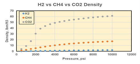
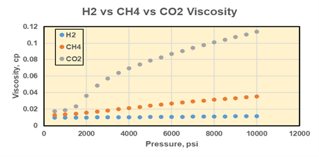
Figure 1. (a) Densities of hydrogen, methane, and CO2 as a function of pressure at 150°F. (b) Viscosities of hydrogen, methane, and CO2 as a function of pressure at 150°F. From Delshad et al. (2021).
Reservoir simulation perormed by Drs. Delshad and Sepehrnoori illustrates the difference between injecting hydrogen and injecting CO2. The Cranfield site in Mississippi has been studied extensively for CO2 storage. This location is a depleted oilfield in a dome structure with 4-way closure (Fig. 2). The hydrogen study focused on an area on the northeast flank of the dome with detailed porosity and permeability constraints (Fig. 3). Comparing 3 years of CO2 and hydrogen injection, hydrogen clearly occupies more of the reservoir and migrates more easily updip (Fig. 4).
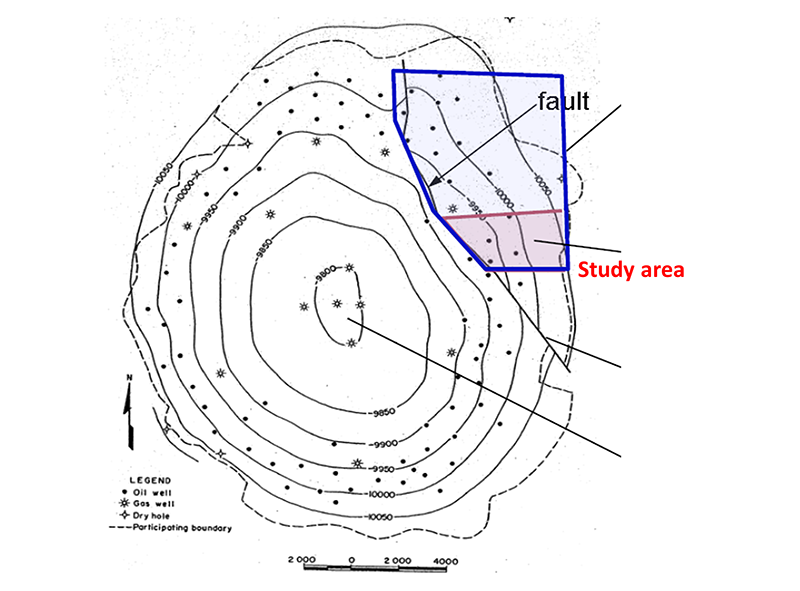
Figure 2. Structure map of Cranfield site. From Hovorka et al. (2013).

Figure 3. Cranfield study area distributions of porosity (a) and permeability (b).
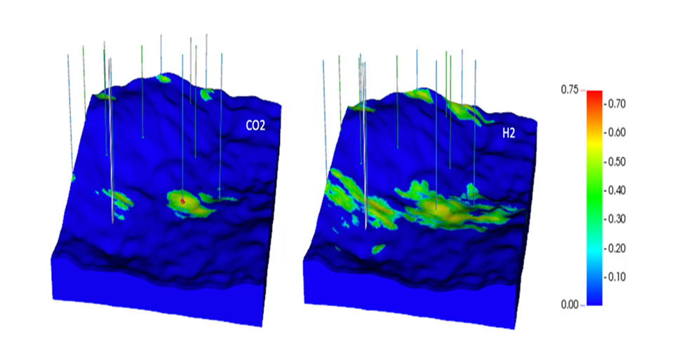
Figure 4. Gas saturations after 3 years of CO2 injection (a) and hydrogen injection (b).
The similarities and differences between hydrogen and CO2 injection illustrate the need for detailed characterization and reservoir simulation, even in areas that have previously been investigated for carbon storage. In addition, more work needs to be done to understand the effect of saturation hysteresis over multiple injection-withdrawal cycles; seal capacity and seal failure due to interactions between hydrogen and rock; microbial processes that can turn hydrogen into methane or acetate during storage; and monitoring techniques for storage sites.
Using hydrogen as a fuel first requires that it be generated, since it does not accumulate naturally in the subsurface like hydrocarbon gas. So-called blue hydrogen is generated from natural gas through various processes including steam methane reforming, authothermal reforming, gas-heated reforming, and partial oxidation. In all these processes, CO2 is generated along with hydrogen. For steam methane reforming, 1 mole of CO2 is produced for every 4 moles of H2, while for partial oxidation the ratio is 1 mole CO2 per 3 moles of H2 (US DOE, 2022). Additional CO2 is generated in the production of energy to drive the process, typically by combusting some of the gas feedstock stream. Further emissions of greenhouse gases occur in the form of methane leaks in the gas supply chain leading to the hydrogen generation facility. Overall, blue hydrogen generation could be associated with significant atmospheric carbon emissions.
Carbon capture and sequestration technology can greatly reduce the carbon emissions associated with blue hydrogen. Technology already used in coal-fired power plants to capture CO2 from flue gas streams can be used in blue hydrogen generation facilities, and the captured CO2 can then be injected underground. The question is then how efficient the CO2 capture can be, and whether carbon capture and sequestration is sufficient to mitigate the carbon footprint of the natural gas supply chain. Dr. Arvind Ravikumar in CSEE investigates life-cycle assessments of blue hydrogen in terms of equivalent CO2 emissions per kilogram of hydrogen generated, considering emissions both from the natural gas supply and hydrogen generation process. His work has demonstrated how even relatively inefficient carbon capture and sequestration (55% efficiency) can yield significant reductions in equivalent CO2 emissions from blue hydrogen generation (Fig. 5). This serves to guide future research in process improvement and more comprehensive life-cycle assessments of hydrogen generation processes.
Figure 5. Comparison of total carbon emissions from hydrogen generation under various scenarios. Grey H2 = hydrogen generation with no carbon capture and sequestration (CCS). MJLHV refers to energy content of the generated hydrogen in terms of lower heating value (LHV), the energy content of the original feedstock gas retained in the generated hydrogen. CO2-eq is equivalent CO2 emissions, combining both CO2 generated at the hydrogen plant and methane emissions. GWP is global warming potential or 20 or 100 years (GWP 20 and GWP 100). Figure from Bauer et al. (2022).
References
Bauer, C., Treyer, K., Antonini, C., Bergerson, J., Gazzani, M., Gencer, E., Gibbins, J., Mazzotti, M., McCoy, S.T., McKenna, R., Pietzcker, R., Ravikumar, A.P., Romano, M.C., Ueckerdt, F., Vente, J., van der Spek, M., 2022. On the climate impacts of blue hydrogen production. Sustainable Energy Fuels, 6, 66-75. https://doi.org/10.1039/d1se01508g
Delshad, M., Mehrabi, M., Ganjdanesh, R., Eichhubl, P., Umurzakov, Y., Sepehrnoori, K., 2021. Simulations of hydrogen storage in sedimentary geologic formations. GeoGulf Transactions, 71, 45-53.
Hovorka, S.D., Meckel, T.A., Treviño, R.H., 2013. Monitoring a large-volume injection at Cranfield, Mississippi – Project design and recommendations. International Journal of Greenhouse Gas Control, 18, 345-360. https://doi.org/10.1016/j.ijggc.2013.03.021