Carbon Capture and Storage (CCS) is a proposed method to reduce anthropogenic carbon dioxide in the atmosphere by capturing CO2 emissions (e.g. from power plants) and storing CO2 in a supercritical state in subsurface geological formations such as deep saline aquifers or depleted hydrocarbon reservoirs.
A number of technical and economic challenges have prevented CCS from being a more widespread solution to reducing CO2 emissions including, cost of capture from power plants, cost of transportation to storage sites, injection at rates that are significant, sufficient storage volume, and potential migration pathways through abandoned wells and non-sealing faults. In the Center for Subsurface Energy and the Environment (CSEE), we are providing solutions to these problems.
In a project with ExxonMobil, we are working on “Estimation of CO2 Storage Efficiency and Migration through Faults”. In the project we are considering different environments of deposition (EOD) for CO2 storage, focusing on deltaic and shoreface environments, guided by typical examples from the Gulf Coast. Small-scale, but high-resolution facies models for a variety of depositional facies are generated and simulated. Expected CO2 saturations and concentrations are benchmarked in different EODs, and that information is used to estimate storage efficiencies in larger-scale systems. We are performing experimental tests of water-CO2 flow through rocks representative of faults and fault gouge with the objective of measuring deformation, capillary pressure, trapping, relative permeabilities, and potential mineral dissolution-precipitation mechanisms. The experiments target mudrocks and sandstones representative of Gulf of Mexico sediments. Complementary numerical simulation models are developed to verify the geomechanical integrity of neighboring faults. Figure 1 shows the results of the modeling effort which uses machine learning to determine the optimal well locations and rates in a faulted reservoir. Furthermore, the sensitivity of storage capacity and the amount of CO2 stored by capillary trapping and solubilization, along with amounts of CO2 migrated, are performed with mechanistic reservoir simulation.
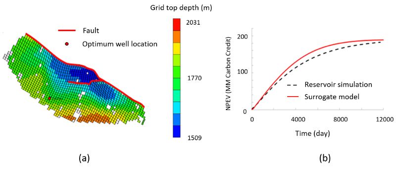
Figure 1. (a) Location of the CO2 injector that results in the maximum NPEV within the field. (b) Comparison between the reservoir simulation and the neural network surrogate model.
The CO2 Capture Project (CCP) “is a group of major energy companies working together to advance the technologies that will underpin the deployment of industrial-scale CO2 capture and storage (CCS) in the oil & gas industry.” https://www.co2captureproject.org/. In collaboration with CCP, we are developing a process that uses a permeability modifier (silica gel and crosslinked polymer) as a conformance control agent and cap rock sealant. Microfluidics and high-pressure, high temperature (HPHT) core flood experiments with CO2 are performed to measure the reactive transport of the modifiers. The results are upscaled in a numerical reservoir simulator is performed to optimize the treatment method for fracture sealing and leakage remediation. The effects of operating conditions, reservoir heterogeneity, and associated uncertainty on the treatment results were investigated by performing sensitivity analysis of the injection time, injection rate, silica concentration, reaction frequency factor, average reservoir permeability, and spatial correlation length. Figure 2 shows the CO2 migration over time in the base case due to crosslinked polymer gel treatment (red) and silica gel treatment (blue dash), and comparison with no gel treatment (black). The top view of the permeability reduction factor Rf for the first grid block layer below caprock is shown and corresponds to the end of the crosslinked polymer treatment period (Zhu et al., 2020).
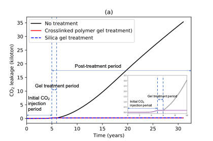
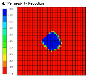
Figure 2. (a) CO2 leakage over time in the base case due to crosslinked polymer gel treatment (red) and silica gel treatment (blue dash), and comparison with no gel treatment (black). The inset is the same plots for 0-10 years. (b) Top view of the permeability reduction factor Rf for the first grid block layer below caprock. The snapshot corresponds to the end of the crosslinked polymer treatment period (Zhu et al., 2020)
Successful subsurface disposal of various fluids, such as CO2, depends on the integrity of the storage site. In a storage site, injection wells and pre-existing wells might leak due to over-pressurization, mechanical/chemical degradation, and/or a poor cement job, thus reducing the sealing capacity of the site. Wells that leak due to microannuli or cement fractures on the order of microns are difficult to seal with typical workover techniques. In a recent DOE project “Novel Materials for Robust Repair of Leaky Wellbores in CO2 Storage Formations” we developed a polyacrylic acid sealant gel that has low viscosity at low pH, but when injected into microannuli of abandoned wellbores (potential CO2 leakage sites), it reacts with cement and viscosifies, thus sealing the leak (Figure 3). We proved the sealant is effective in the laboratory and performed computational fluid dynamics simulations. We collaborated with the Carbon Capture Project (CCP) to test our sealant at their test well in Mont Terri, Switzerland and the polymer gel sealant was injected to seal a leaky wellbore drilled in the Opalinus Clay as a pilot test. The results showed more than a ten-fold drop in the injection rate compared to the case without the sealant.
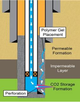
Figure 3. Leakage pathway in fractured cement annulus (left) and polymer gel placement through perforation to seal leakage (right).
We have also developed a general modelling tool for the analysis of fault slippage in large-scale CO2 sequestration projects (Tavassoli et al., 2018) using the Embedded Discrete Fracture Model (EDFM) (Hearn et al, 1997; Moinfar et al., 2014; Xu et al., 2019) for describing leaky faults. An illustration of the CO2 saturation profile using this technique is presented in Figure 4. Furthermore, IPHREEQc, a rigorous geochemistry module developed by USGS, has been coupled with our reservoir simulators to accurately model the reactive-transport and interactions between CO2, brine and rock (Korrani, 2014; Sanaei, 2019). With this model, CO2 dissolution in the aqueous phase is better modeled. Other effects such clay swelling, scale deposition, changes in porosity and permeability are also possible to simulate with this tool. Finally, the effects of changing brine composition are also considered, allowing the evaluation of projects where CO2 is injected along with brine fraction.
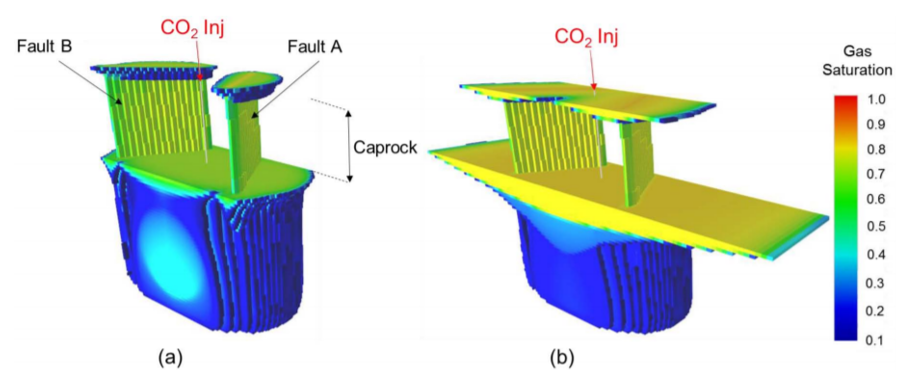
Figure 4. Gas saturation profile for a CSS simulation considering two leaky faults simulated with EDFM. (a) After 50 years of simulation; (b) after 1,000 years of simulation.
References
- Tavassoli, S.*, Ho, J.F., Shafiei, M., Huh, C., Bommer, P, Bryant, S., Balhoff, M. “An Experimental and Numerical Study of Wellbore Leakage Mitigation using pH-Triggered Polymer Gelant”, Fuel, Volume 217, Issue 1, pages 444-457, April 2018, DOI: https://doi.org/10.1016/j.fuel.2017.12.098
- Shafei, M., Bryant, S., Balhoff, M. Huh, C., Bonnecaze, R.* "Hydrogel Formulation for Sealing Cracked Wellbores for CO2 Storage", Applied Rheology, Volume 27, Issue 6, pages 64433:1-8, September 2017, DOI: 10.3933/ApplRheol-27-64433
- Ho, J.F., Patterson, J.W, Tavassoli, S. Shafei, M., Balhoff, M.T.*, Huh, C. Bommer, P.M., Bryant, S.L., “The Use of a pH-Triggered Polymer Gelant to Seal Cement Fractures in Wells”, SPE Drilling and Completions, Volume 31, Issue 3, pages 225-235, September 2016, http://dx.doi.org/10.2118/174940-PA
- Tavassoli, S., Shafei, M., Minnig, C., Gisiger, J., Rosili, U., Patterson, J., Theurillat, T., Mejia, L., Goodman, H., Espie, T., Balhoff, M., “Pilot Case Study of Wellbore Leakage Mitigation using pH-Triggered Polymer Gelant, SPE-194251-MS was prepared for presentation at the SPE/ICoTA Well Intervention Conference and Exhibition held in The Woodlands, TX, USA, 26-27 March 2019.
- Zhu, P.*, Tavassoli, S., Ryu, J.; Pyrcz,, Balhoff, M.T., “Injection of Gel Systems for CO2 Leakage Remediation”, International Journal of Oil, Gas, and Coal Technology, 2020 in review.
- Ryu, J., Espinoza, D.N, Balhoff, M.T., Tavassoli, S., “Simulation of Fault Reactivation using the HISS Model”, SPE prepared for presentation at the 2019 SPE Annual Technical Conference and Exhibition held in Calgary, Canada, September 30, 2019 – October 2, 2019.
- Tavassoli, S., Xu, Y., Sepehrnoori, K., Modeling Fault Reactivation using the Embedded Discrete Fracture Method, presented at the 2018 SPE Annual Technical Conference and Exhibition held in Dallas, USA, September 24-26, 2018.
- Hearn, C.L., Al-Emadi, I.A.A., Worley, P.L.H., Taylor, R.D., Improved Oil Recovery in a Tight Reservoir with Conductive Faults, ISND Shuaiba, Qatar, presented at the SPE Annual Technical Conference and Exhibition held in San Antonio, USA, October 5-8, 1997.
- Moinfar, A., Varavei, A., Sepehrnoori, K., Johns, R.T., Development of an Efficient Embedded Discrete Fracture Model for 3D Compositional Reservoir Simulation in Fractured Reservoirs, SPE Journal, Volume 19, Issue 2, pages 289-303, April 2014.
- Xu, Y., Fernandes, B.R.B, Marcondes, F., Sepehrnoori, K., Embedded Discrete Fracture Modeling for Compositional Reservoir Simulation using Corner-Point Grids, Journal of Petroleum Science and Engineering, Volume 177, pages 41-52, June 2019.
- Korrani, A.K.N., Mechanistic Modeling of Low Salinity Water Injection, PhD Dissertation, The University of Texas at Austin, USA, 2014.
- Sanaei, A., Compositional Reactive-Transport Modeling of Engineered Waterflooding, PhD Dissertation, The University of Texas at Austin, USA, 2019.